|
|
|
Who's Online
There currently are 5946 guests online. |
|
Categories
|
|
Information
|
|
Featured Product
|
|
|
 |
|
|
There are currently no product reviews.
 ;
Thanks to this service manual I repaired my old camcorder! The manual perfectly explains how to disassemble the camcorder step by step.
;
This manual is very useful because it presents the technical specifications of the cd player, including the manufacturer of the reader, this helps if you need to replace it. It also displays the settings and layout of the circuit.
;
Manual was a good representation of service infomation for the EWV404. It worked well for my repair.
 ;
Great quality copy, right what I was looking for, all I need to fix my radio.
Thanks
;
I BOUGHT A PAIR OF INFINITY VINTAGE SPEAKERS THAT REQUIRED TO BE REPAIRED AND THE ELECTRONIC TECHNICIAN ASKED ME FOR THE SERVICE MANUAL.
I TRIED TO GET IT AT THE MANUFACTURER'S SITE WITH NO SUCCESS, SO I STARTED TO LOOK FOR IT IN THE WEB FOR A LONG TIME, UNTIL I FOUND THE SERVICE MANUAL IN THIS EXCELLENT SITE "OWNER'S MANUAL.COM".
NOW I HAVE MY SPEAKERS WORKING AND ENJOYING THE MUSIC I LIKE.
THANKS TO "OWNER`S MANUAL.COM" I RECOMMEND THIS SITE TO EVERYONE.
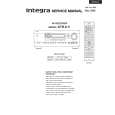
DTR-6.5
Confirmation of protection circuit
1. Confirmation of speaker relay
Confirm that the speaker relays turn ON approximately 5 seconds after the power switch is turned ON. Confirm that the speaker relays turn OFF immediately after the power switch is turned OFF.
2. How to enter Test Mode
1. To enter a test mode (Test 1 to 4), when the unit is turned on, hold down "CD" + "DISPLAY" buttons and then press "STANDBY/ON" button. 2. Press the respective designated buttons and make sure that your target mode starts. Left arrow key Right arrow key
Zone 2
Standby
Mode Test-1 Test-2 Test-3 Test-4
Button to be pressed "DVD" "VIDEO 1" "VIDEO 2" "VIDEO 3"
Message to be shown on the Front display "Test-1-00" "Test-2-00" "TUNER 82" "Test-4-00"
To move to the next step, press the right arrow key. When you enter Test-3, it is necessary to press this button once to see "Test-3-00" is shown. To move to the previous step, press the left arrow key. To exit, press "STANDBY/ON" button.
3.Confirmation of protection circuit
Check of Voltage detection 1. Enter Test-4 mode. 2. Press and release the right arrow key repeatedly until "TEST-4-21" is shown on the Front display. 3. See your unit automatically start to check each channel. During the check, the message on the display is changing as follows: Channel 1st Message 2nd Message FL+ TEST-4-21 Protect OK FR- TEST-4-22 Protect OK C+ TEST-4-23 Protect OK SL- TEST-4-24 Protect OK SR+ TEST-4-25 Protect OK SBL- TEST-4-26 Protect OK SBR+ TEST-4-27 Protect OK When the whole check is completed, "TEST-4-35" is shown. 4. Exit from the test mode. Check of Current detection 1. Enter Test-4 mode. 2. Press and release the right arrow key repeatedly until "TEST-4-35" is shown on the Front display. 3. Connect a 3 ohm hollow resistor to a speaker terminal for each channel and make sure that the speaker relay would not cut off. 4. Connect a 1.5 ohm hollow resistor to a speaker terminal for each channel and make sure that the speaker relay would cut off. 5. Exit from the test mode.
|
|
|
> |
|